


ترنسدیوسر ارتعاش Eddy Current مدل SHINKAWA FK-302F
مبدل های ارتعاش FK برای اندازه گیری جابجایی محوری به سطح فولادی طراحی شده اند. مبدل های سری FK نشان دهنده لبه برش طراحی پروب مجاورت جریان گردابی است. سری FK به طور کامل الزامات استاندارد 670 موسسه نفت آمریکا (API-670) را برآورده می کند و طراحی مقاوم آن سال ها خدمات بدون مشکل را تضمین می کند

Conventional designation of the FK-302F transmitter:
| FK- | 302 | F | 1,2 |
FK : 452
1 or 2: maximum length of FW cable:
symbol “1” – 5 m;
symbol “2” – 9 m;
symbol “3” – 7 m

Purpose
Vibration transducers FK (hereinafter referred to as transducers) are designed to measure axial displacement to a steel surface.
Description
Structurally, FK vibration transducers consist of an FL or WL sensor (hereinafter referred to as the sensor), an FW or WW cable (hereinafter referred to as the cable) and an FK transmitter (hereinafter referred to as the transmitter).
The principle of operation of the converters is as follows: a change in the distance from the end of the converter sensor to the steel surface over which it is installed causes changes in the electromagnetic induction inside the sensor. These changes in magnetic induction are converted into an electrical signal, which is amplified and converted by the transmitter into an output signal in the form of DC voltage.
The converters are produced in nine modifications, differing in the ranges of axial displacement measurements, which are presented in Table 1.
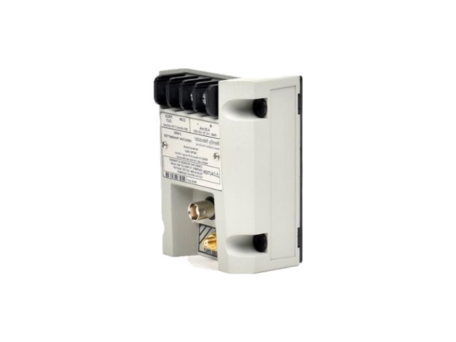
Serial numbers of transmitters in the form of alphanumeric designations consisting of Latin alphabet characters and Arabic numerals are applied to the label on the transmitter body using the printing method, as shown in Figure 1.
The sensor and cable are a single, non-separable structure, and the serial numbers of the sensors in the form of alphanumeric designations consisting of Latin alphabet characters and Arabic numerals are applied to the label on the cable body using printing, as shown in Figure 2.
The design does not provide for the application of a verification mark on the converter.
Sealing against intentional and/or unintentional interference that may affect the measurement results is carried out at the manufacturing plant upon release from production by the gluing method. The locations of the seals applied by the manufacturer are shown in Figure 4.
Place of application of serial number of transmitters
Figure 1 - General view of FK vibration transducers and location of serial numbers of transmitters
Figure 2 – General view of the cable
Figure 3 - Location of the serial number of the sensors
Conventional designation of the FK transmitter:
| FK- | 1 | F | 1 OR 2 |
1: transmitter modification: 143, 202, 263, 452, 602.
2 or 1: maximum length of FW cable:
symbol "1" : 5 m;
symbol "2" - 9 m.
Conventional designation of the FK-302F transmitter:
| FK- | 302 | F | 1,2 |
FK : 452
1 or 2: maximum length of FW cable:
symbol "1" - 5 m;
symbol "2" - 9 m;
symbol "3" - 7 m
Conventional designation of the FK-152R transmitter:
| FK- | 152R | R | 1/2 |
FK :152
1 or 2 maximum length of FW cable:
symbol "1" - 15 m;
symbol "2" - 20 m.
Conventional designation of the FK-142K transmitter:
| FK- | 143 | F | 1 or 2 |
1 - maximum length of FW cable:
symbol "1" - 5 m;
symbol "2" - 7 m.
Symbolic designation of the FL-202F05 sensor:
FL-202F05 1 - 2 -3-4-5
| 1 | 2 | 3 | 4 | 5 |
1 - protective coating:
symbol "L" - without protection;
symbol "A" - with protection, but without fluororubber coating;
symbol "T" - with protection and fluororubber coating.
2 - thread size:
symbol "M1" - M8*1;
symbol "U1" - 1/4-28UNF.
3 - thread pitch, mm.
4 - body length, mm.
5 - actual cable length:
"05" - 0.5 m;
"10" - 1 m;
"50" - 5 m;
"90" - 9 m.
Symbolic designation of the FL-202F08 sensor:
FL-202F08 1 - 2 -3-4-5
| 1 | 2 | 3 | 4 | 5 |
1 - protective coating:
symbol "L" - without protection;
symbol "A" - with protection, but without fluororubber coating;
symbol "T" - with protection and fluororubber coating.
2 - thread size:
symbol "M2" - M10*1;
symbol "U2" - 3/8-24UNF.
3 - thread pitch, mm.
4 - body length, mm.
5 - actual cable length:
"05" - 0.5 m;
"10" - 1 m;
"50" - 5 m;
"90" - 9 m.
Symbolic designation of the FL-202F08R sensor:
FL-202F08R 1 - 2 - 3 – 4
| 1 | 2 | 3 | 4 | 5 |
1 - thread size:
symbol "M2" - M10*1;
symbol "U2" - 3/8-24UNF.
2 - cable length
symbol "R5" - 5 mm;
symbol "02" - 0.2 inches.
3 - length of the case
symbol "03" - 30 mm;
symbol "12" - 1.2 inches.
4 - actual cable length:
"05" - 0.5 m;
"10" - 1 m;
"50" - 5 m;
"90" - 9 m.
Symbolic designation of the FL-452F11 sensor:
FL-452F11 1 - 2 -3-4-5
| 1 | 2 | 3 | 4 | 5 |
1 - protective coating:
symbol "L" - without protection;
symbol "A" - with protection, but without fluororubber coating;
symbol "T" - with protection and fluororubber coating.
2 - thread size: symbol
"M1" - M14 1.5;
symbol "U1" - 1/2-20UNF.
3 - thread pitch, mm.
4 - body length, mm.
5 - actual cable length:
"05" - 0.5 m;
"10" - 1 m; "50" - 5 m;
"90" - 9 m.
Symbolic designation of the FL-302F10 sensor:
FL-302F10 1 - 2 -3-4-5
| 1 | 2 | 3 | 4 | 5 |
1 - protective coating:
symbol "L" - without protection;
symbol "A" - with protection, but without fluororubber coating;
symbol "T" - with protection and fluororubber coating.
2 - thread size:
symbol "M1" - M12I.25;
symbol "U1" - 1/2-20UNF.
3 - thread pitch, mm.
4 - body length, mm.
5 - actual cable length:
"05" - 0.5 m;
"10" - 1 m;
"50" - 5 m;
"90" - 9 m.
Symbolic designation of the FL-302F10R sensor:
FL-302F10R 1 - 2 - 3 – 4
| 1 | 2 | 3 | 4 | 5 |
1 - thread size:
symbol "M2" - M10*1;
symbol "U2" - 3/8-24UNF.
2 - length without thread
"R2" - 2 mm;
symbol "01" - 0.1 inch.
3 - length of the case
"03" - 25 mm;
symbol "10" - 1.0 inch.
4 - actual cable length:
"05" - 0.5 m;
"10" - 1 m;
"50" - 5 m;
"90" - 9 m.
Symbolic designation of the FL-602F18 sensor:
FL-602F18 1 - 2 -3-4-5
| 1 | 2 | 3 | 4 | 5 |
1 - protective coating:
symbol "L" - without protection;
symbol "A" - with protection, but without fluororubber coating;
symbol "T" - with protection and fluororubber coating.
2 - thread size:
symbol "M1" - M20*1.5;
symbol "U1" - 7/8-14UNF.
3 - thread pitch, mm.
4 - body length, mm.
5 - actual cable length:
"05" - 0.5 m;
"10" - 1 m; "50" - 5 m;
"90" - 9 m.
Symbolic designation of the FL-143F27 sensor:
FL-143F27 1 - 2 -3-4-5
| 1 | 2 | 3 | 4 | 5 |
1 - protective coating:
symbol "L" - without protection;
symbol "A" - with protection, but without fluororubber coating;
symbol "T" - with protection and fluororubber coating.
2 - thread size:
symbol "M1" - M30 1.5;
symbol "U1" - 1 1/4-12UNF.
3 - thread pitch, mm.
4 - body length, mm.
5 - actual cable length:
"05" - 0.5 m;
"10" - 1 m;
"50" - 5 m;
"90" - 9 m.
Symbolic designation of the FL-143F28 sensor:
FL-143F28 1 - 2 -3-4-5
| 1 | 2 | 3 | 4 | 5 |
1 - protective coating:
symbol "L" - without protection;
symbol "A" - with protection, but without fluororubber coating;
symbol "T" - with protection and fluororubber coating.
2 - thread size:
symbol "M1" - 4-M6,
DEPTH 14
3 - thread pitch, mm.
4 - body length, mm.
5 - actual cable length:
"05" - 0.5 m;
"10" - 1 m;
"50" - 5 m;
"90" - 9 m.
Symbolic designation of the FL-263F50 sensor:
| FL-263F50 | 1 | - | 2 | - | 3 | - | 4 | - | 5 | |
| 1 - protective coating: symbol "L" - without protection; symbol "A" - with fluororubber protection; symbol "T" - with protection and fluororubber coating.
2 - thread size: symbol "M1" - M24*1.5; symbol "U1" - 1-12UNF. 3 - thread pitch, mm. 4 - body length, mm. 5 - actual cable length: "05" - 0.5 m; "10" - 1 m; "50" - 5 m; "90" - 9 m. Symbolic designation of the FL-263F55 sensor: |
but without coating | |||||||||
| FL-263F55 | 1 | - | 2 | - | 3 | - | 4 | - | 5 | |
| 1 - protective coating: symbol "L" - without protection; symbol "A" - with fluororubber protection; symbol "T" - with protection and fluororubber coating.
2 - thread size: symbol "M1" - M24I.5 3 - thread pitch, mm. 4 - body length, mm. 5 - actual cable length: "05" - 0.5 m; "10" - 1 m; "50" - 5 m; "90" - 9 m. Symbolic designation of the FL-152F08 sensor: |
but without coating | |||||||||
| FL-152F08 | 1 | - | 2 | - | 3 | - | 4 | - | 5 | |
1 - protective coating:
symbol "L" - without protection;
symbol "A" - with protection, but without fluororubber coating;
symbol "T" - with protection and fluororubber coating.
2 - thread size:
symbol "M2" - M10*1;
symbol "U2" - 3/8-24UNF.
3 - thread pitch, mm.
4 - body length, mm.
5 - actual cable length: "005" - 0.5 m; "010" - 1 m; "150" - 15 m; "200" - 20 m.
Symbolic designation of the FL-1502F08R sensor:
FL-152F08R 1 - 2 - 3 – 4
| FL-1502F08R | 1 | 2 | 3 | 4 |
1 - thread size:
symbol "M2" - M10*1;
symbol "U2" - 3/8-24UNF.
2 - length without thread
symbol "R5" - 5 mm;
symbol "02" - 0.2 inches.
3 - length of the case
symbol "03" - 30 mm;
symbol "12" - 1.2 inches.
5 - actual cable length:
"005" - 0.5 m;
"010" - 1 m;
"150" - 15 m;
"200" - 20 m.
Symbolic designation of the WL-142K05 sensor (for the FK-142K transmitter):
WL-142K05 1 - 2 -3-4-5
| WL-142K05 | 1 | 2 | 3 | 4 |
1 - protective coating:
symbol "L" - without protection;
symbol "A" - with protection, but without fluororubber coating;
symbol "T" - with protection and fluororubber coating.
2 - thread size:
symbol "M1" - M8*1;
symbol "M2" - M10*1;
symbol "U1" - 1/4-28UNF-2A;
symbol "U2" - 3/8-24UNF-2A.
3 - thread pitch, mm.
4 - body length, mm.
5 - actual cable length:
"1" - 0.5 m;
"2" - 1 m;
"3" - 5 m;
"4" - 7 m.
Symbolic designation of the WL-142K05R sensor (for the FK-142K transmitter):
WL-142K05R 1 - 2 - 3 – 4
| WL-142K05R | 1 | 2 | 3 | 4 |
1 - thread size:
symbol "M2" - M10*1;
symbol "U2" - 3/8-24UNF-2A.
2 - thread pitch, mm.
3 - body length, mm.
4 - actual cable length:
"1" - 0.5 m;
"2" - 1 m;
"3" - 5 m;
"4" - 7 m.
Conventional designation of FW cable:
| FW | 1 | F | 2 | 3 |
1 - transmitter modification: 143, 202, 263, 452, 602.
2 - protective coating:
symbol "L" - without protection;
symbol "A" - with protection, but without fluororubber coating;
symbol "T" - with protection and fluororubber coating.
3 - actual cable length:
"40" - 4.0 m;
"45" - 4.5 m;
"80" - 8.0 m;
"85" - 8.5 m.
Conventional designation of cable FW-302F:
FW-302F1-2
| FW | 302 | F | 1 | 2 |
1 - protective coating:
symbol "L" - without protection;
symbol "A" - with protection, but without fluororubber coating;
symbol "T" - with protection and fluororubber coating.
2 - actual cable length:
"40" - 4.0 m;
"45" - 4.5 m;
"80" - 8.0 m;
"85" - 8.5 m;
"E0" - 14.0 m;
"E5" - 14.5 m.
Conventional designation of the FW-152R cable:
FW-152R1-2
| FW | 152 | R | 1 | 2 |
1 - protective coating:
symbol "L" - without protection;
symbol "A" - with protection, but without fluororubber coating;
symbol "T" - with protection and with fluororubber coating.
2 - actual cable length:
"140" - 14.0 m;
"145" - 4.5 m;
"190" - 19.0 m;
"195" - 19.5 m;
Conventional designation of cable WW-142K:
WW - 142 K 1 - 2
| WW | 142 | K | 1 | 2 |
1 - protective coating:
symbol "L" - without protection;
symbol "A" - with protection, but without fluororubber coating;
symbol "T" - with protection and fluororubber coating.
2 - actual cable length:
"1" - 4.0 m;
"2" - 4.5 m;
"3" - 6.0 m;
"4" - 6.5 m
Technical specifications
Table 1 - Metrological characteristics____________________________________________
| Name of the characteristic | Meaning | ||||||||
| Modification | |||||||||
| FK-
152R1,2 |
FK-302F3 | FK-202F1,2 | FK-452F1,2 | FK-302F1,2 | FK-602F1,2 | FK-143F 1,2 | FK-263F1,2 | FK-142K 1,2 | |
| Axial displacement measurement range, mm | from 0.25 to 1.75 | from 0.25 to 3.25 | from 0.25 to 2.55 | from 0.5 to 5.0 | from 0.25 to 3.25 | from 0.5 to 6.5 | from 3.0 to 16.5 | from 3 to 29 | from 0.4 to 1.8 |
| Nominal conversion factor, V/mm | 7.87 | 5.0 | 7.87 | 3.94 | 5.0 | 2.5 | 0.8 | 7.87 | |
| Operating frequency range, Hz | from 0.2 to 7000 | from 0.2 to 8000 | from 0.2 to 10000 | ||||||
| Limits of permissible deviation of the actual value of the conversion factor from the nominal value, % | ±4 | ||||||||
| Nonlinearity of the amplitude characteristic, %, no more than | ±5.01); ±6.52) | ±10 | ±10 | ±5 | - | - | - | ±10 | ±12.5 |
End of table 1________________________________________________________________
| Name of the characteristic | Meaning | ||||||||
| M | modification | ||||||||
| FK-152R1, 2 | FK-302F 3 | FK-202F1, 2 | FK-452F1, 2 | FK-302F1, 2 | FK-602F1, 2 | FK-143F1, 2 | FK-263F1, 2 | FK-142K1, 2 | |
| Frequency response unevenness, dB, no more than | ±3 | ||||||||
| 1) - for FK vibration transducers with 5 m long FW cable
2) - for FK vibration transducers with 9 m long FW cable |
|||||||||
Table 2 - Main technical characteristics
| Name of the characteristic | Meaning |
| DC supply voltage, V | 24.0±2.4 |
| Operating conditions of measurements (for sensors): - ambient temperature, °C - relative humidity, %, - atmospheric pressure, kPa | from -40 to +80 from 30 to 95 from 84 to 106 |
| Operating conditions of measurements (for transmitters): - ambient temperature, °C - relative humidity, %, - atmospheric pressure, kPa | from +15 to +35 from 45 to 80 from 84 to 106 |
| Overall dimensions of sensors (excluding cable), mm, no more than:
- diameter - length |
50
250 |
| Overall dimensions of transmitters, mm, no more than: - length - height - width | 81
75 35 |
| Weight of the converter (including cable), kg, no more than | 5 |
| Average service life, years, not less than | 10 |
Type approval mark
is applied to the title page of the operating documentation using a typographic method
Completeness
Table 3 - Completeness of the measuring instrument
| Name | Designation | Quantity |
| Sensor | FL or WL1) | 1 pc. |
| Transmitter | FK1) | 1 pc. |
| Cable | FW or WW1) | 1 pc. |
| User manual | Vibration converters FK. Operation manual. | 1 copy. |
| 1) - the modification designation is determined in accordance with the order | ||
Information on measurement methods
are presented in section 2.2 “Principle of measurements” of the document
"FK Vibration Converters. Operation Manual".
Regulatory documents
Order of Rosstandart dated December 27, 2018 No. 2772 "On approval of the state verification scheme for measuring instruments of vibration displacement, vibration velocity, vibration acceleration and angular acceleration";
FK-001-2021 STP "FK Vibration Converters. Enterprise Standard".

 فلومتر التراسونیک
 فلومتر مغناطیسی
 فلومتر مکانیکی
 فلومتر جرمی حرارتی
 فلومتر جرمی کوریولیس
 فلومتر توربین
 فلومتر ورتکس
 روتامتر
 دبی سنج پدالی


دیدگاهها
پاکسازی فیلترهیچ دیدگاهی برای این محصول نوشته نشده است.